


Bagikan :
Bagikan :
- Switch & Controller
- Schmersal Safe Switching AES 2135


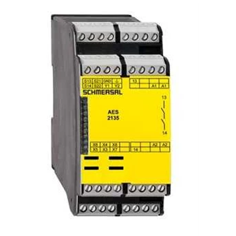
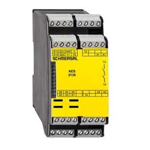
Schmersal Safe Switching AES 2135
Update Terakhir
:
01 / 12 / 2019
Min. Pembelian
:
1 Unit
Harga
CALLBagikan
:
Multi Sarana Industrindo sebagai agent dan distributor berbagai kebutuhan perusahaan anda dengan bermacam-macam merk dan product
Detail Schmersal Safe Switching AES 2135
Ordering details
Product type description
AES 2135
Article number
1180842
EAN code
4030661314914
Approval
Approval
BG
USA/ CAN
Classification
Standards
EN ISO 13849-1, IEC 61508
PL
up d
PFH value
1.0 x 10⁻⁷/ h
SIL
up 2
Mission time
20 Years
PFHd
Switching frequency c
Control category
up 3
MTTFd
Classification
PDF-M
Global Properties
Product name
AES 213x
Standards
IEC/ EN 60204-1, EN 60947-5-1, IEC 60947-5-3, IEC 61508, BG-GS-ET-14, BG-GS-ET-20
Compliance with the Directives ( Y/ N)
Yes
Climatic stress
IEC 60947-5-3, BG-GS-ET-14
Mounting
snaps onto standard DIN rail to EN 60715
Terminal designations
IEC/ EN 60947-1
Materials
- Material of the housings
Plastic, glass-fibre reinforced thermoplastic
- Material of the contacts
Ag-Ni,
Weight
280 g
Start input ( Y/ N)
No
Feedback circuit ( Y/ N)
No
Start-up test ( Y/ N)
No
Reset after disconnection of supply voltage ( Y/ N)
Yes
Automatic reset function ( Y/ N)
Yes
Reset with edge detection ( Y/ N)
No
Pull-in delay
- ON delay with automatic start
adjustable 0, 1 / 1.0 s
Drop-out delay
- Drop-out delay in case of emergency stop
0 piece
Number of openers
adjustable 1 piece -> 2 piece
Input resistance
approx. 4000 © at GND
Input signal " 1"
10 ... 30 VDC
Input signal " 0"
0 ... 2 VDC
Cable length
1000 m with 1.5 mm² ( for Rated voltage)
Outputs
Stop category
0
Number of safety contacts
1 piece
Number of auxiliary contacts
0 piece
Number of signalling outputs
2 piece
Switching capacity
- Switching capacity of the safety contacts
min. 10 mA, max. 4 A
- Switching capacity of the signaling/ diagnostic outputs
Y1, Y2 = 100 mA
Fuse rating
- Protection of the safety contacts
4 A gG D-fuse
- Fuse rating for the signaling/ diagnostic outputs
short-circuit proof
Signalling output
Y1: ( X5 / X6 without bridge) Authorized operation ( X5 / X6 with bridge) guard open
Y2: ( X5 / X6 without bridge) None Authorized operation ( X5 / X6 with bridge) Error
Utilisation category To EN 60947-5-1
AC-15: 230 V / 3 A
DC-13: 24 V / 2 A
Number of undelayed semi-conductor outputs with signaling function
2 piece
Number of undelayed outputs with signaling function ( with contact)
0 piece
Number of delayed semi-conductor outputs with signaling function.
0 piece
Number of delayed outputs with signalling function ( with contact) .
0 piece
Number of secure undelayed semi-conductor outputs with signaling function
0 piece
Number of secure, undelayed outputs with signaling function, with contact.
0 piece
Number of secure, delayed semi-conductor outputs with signaling function
0 piece
Number of secure, delayed outputs with signaling function ( with contact) .
0 piece
LED switching conditions display
LED switching conditions display ( Y/ N)
Yes
Number of LED´ s
1 piece
Integral system diagnosis ISD
Integral system diagnosis ISD
- The following faults are registered by the safety monitoring modules and indicated by ISD
- Failure of door contacts to open or close
- Cross-wire or short-circuit monitoring of the switch connections
- Interruption of the switch connections
- Failure of the safety relay to pull-in or drop-out
- Fault on the input circuits or the relay control circuits of the safety monitoring module
Miscellaneous data
Applications
Safety sensor
Guard system
Dimensions
Dimensions
- Width
45 mm
- Height
100 mm
- Depth
121 mm
notice
Inductive loads ( e.g. contactors, relays, etc.) are to be suppressed by means of a suitable circuit.
notice - Wiring example
To secure a guard door up to PL 3 and Category # 03#
Monitoring 1 guard door( s) , each with a magnetic safety sensor of the BNS range
Modification for 2 NC contacts:
The safety monitoring module can be modified to monitor two NC contacts by bridging the terminals X3 and X4. The short-circuit recognition between connections then becomes inoperative.
Inversion of the output function:
By establishing a bridge between X5 and X6, the output function of the additional outputs can be altered. This control can also be realised when e.g. a PLC is running ( 24 VDC at terminal X6) .
Expansion of the enable delay time
The enable delay time can be increased from 0, 1 s to 1 s by mounting a jumper connection between the terminals X7 and X8.
The wiring diagram is shown with guard doors closed and in de-energised condition.
The ISD tables ( Intergral System Diagnostics) for analysis of the fault indications and their causes are shown in the appendix.
Tampilkan Lebih Banyak
Produk Lainnya Dari CV. Multi Sarana Industrindo


CV. Multi Sarana Industrindo
Multi Sarana Industrindo sebagai agent dan distributor berbagai kebutuhan perusahaan anda dengan bermacam-macam merk dan product seperti dibawah ini : + GF+ SIGNET, Slow pH, ORP, Conductivity & Ratio Instruments Elcometer + GF+ SLOANE, PVC/ CPVC/ PP Pipes & Fittings, 3D, Precision Test Gauges & Calibration Units, 3M Touch Monitors, 3-STARS, TCT Circular Saws, Diamond Wheels, Knives, A KIRCHNER & TOCHTER, Flow Meters For Gases & Liquids, AALBORG, Variable Area Flowmeter, AALIANT, Target/ Vortex/ Ultrasonic Flowmeters, AALIANT/ HERSEY, Vortex, PD, Target, Magnetic & BTU Meters, ABZ, Butterfly Valves, AC MARINE, Marine Antennas, AC, Filters. ACCU-CODER, Rotary Optical Encoders, ACCULOK, Valves & Fittings, ACE GLAM, Special Glassware, ACEPACK, CD Stud, CD Centre, ACGIH, Industrial Hygiene Publications, ACME, Pipe & Accessories For Concrete Pumps, ACONA, Three & Five Way Manifolds Valves, ACP, Frequency Converters, ACR, Compact Self-Powered Data Loggers, ACROMAG, Signal Conditioners & Data Acquisition Systems, ACS, Alcohol Breath Testers, ACTARIS, Metering Systems, ACTARIS, Water Meters C/ W Pulser, ACTION HOSE COUPLINGS, Quick Action & Safety Hose Couplings, ACUTECH, Engineered Plastics, ADAC, Computer Plug In Data Acquisition Cards & Interface Equipment, ADSENS, Pneumatic Exhaust Mufflers, Filters & Sensors, ADTECH, Signal Converter, Transmitter & Isolator ,ADVANCED ILLUMINATION, Led Back Lights, Board Area, Diffuse, Ring, Spot, Darkfield & Line Lightings For Machine Vision, ADVANTEC TOYO, Industrial & Analytical Filter Papers, SyringeFilters, Membrane Filters, Thimble Filters, Etc, AEC, Industry & Marine Automation, GMDSS, PA, Intercom, Temp. Monitoring, Fire-Alarm, Gas System, AEC, Power Supply, GMDSS Terminal, Gyro Interface, Automation Central Panel, AEC, Shaft RPM, Rudder Angle Meter, Fuel Level Gauge, AEES, Battery Charger, AEG, Sensors, Controls, Switches, AEROQUAL, Handheld Gas Monitors, Gas Monitors For FixedInstallation, AEROQUAL, Ozone Meter, AGAR, Multi-Phase Flowmeters, Water In Oil Monitor, Probes, AGRU, High Purity PVDF Piping Systems, AIC, Display Monitors, Panel Meters, Etc, AIPHONE, Communication & Security Systems, AIR FLOW, Monitor Valves, AIR MITE, Air Arbor Pressess, Pneumatic Cylinders & Valves, AIR TECH PUMP, Regenerative, LH Serie, Orion Dry Rotary, LiquidRing & Medical Vacuum Pump & Systems, AIR TORQUE, Pneumatic Actuators ( Single Or Double Acting), AIRCONTROL TECH, Cooling Systems/ Package, AIRFLOW, Airflow Meters, Air Leakage Testers, Manometers, AIRGAS, Smart Indicating Regulator, Change Over Panel, Super Clean Gas Filter, AIRPAX, Magnetic Speed Sensors, Hall Effect Speed Sensors& Digital Tachometers, AIRSCREW, Fans & Blowers, AKATHERM INTERNATIONAL B V, PP/ PE Drainage Fitting & PP/ PE Pressure Fitting, AKATHERM, HDPE Pipes & Fittings For Drainage, Sison SlphonicRoof Drainage Systems, Akavent Drainage Systems, AKATHERM, PE, Drainage Pipes & Fittings, AKO, Pinch/ Sleeve Valves, AKRON, Nozzles, ALC, Centrifuge, ALCO, Valves & Manifolds, ALCOHOL COUNTERMEASURE SYSTEMS, Alcohol Breath Testers, ALDRICH, Standard & Chemicals, ALEPH HONG KONG, Electronic Components, ALFA MIRAGE, Densimeter, ALFAGOMMA, Industrial Hoses, Hydraulic Hose, ALFOR HAAR, Fuel Components, ALJAC, Basket Strainers, Close Circuit Samplers, ALJAR, Bonding Reels & Sampling Jar, ALKON, Brass Tube Fittings, Tubing & Pneumatic Valves, ALL AMERICAN, Autoclave, ALLEGHENY BRADFORD CORPORATION, Tanks, Filter Housings, ALLENAIR, Brass & SS Pneumatic & Hydraulic Cylinders & Valves, ALL-FLO, Air-Operated Double Diaphragm Pump, ALLTECH, Chromatography, Filtration,ALNOR( TSI) , Anenometers, Balometers, Velometers, A-LOK, Valves & Fittings, ALP, Autoclaves, ALPHA RESOURCES, ICP, AA & Accessories For Elemental Analyzers, ALPHA TECHNOLOGIES, Nickel Plated Tube Fittings, Quick Exhaust & Ball Valves, ALPHA, Safety Couplings, ALVAREZ-REDONDO, Centrifuge, AMCO, Gas Regulators, Meters, AMERICAN METER COMPANY, Gas Regulators, AMETEK JF INSTRUMENTS, Pressure & Temperature Calibration Equipment, AMETEK ROTRON, Fans & Blowers, AMETEK, Gauges & Transducers, AMF, Clamping Systems, AMICO, Bathroom Fixture & Fitting, Water Meter, Mixers, AMOT CONTROLS, Engine Safety System & Panels, Pneumatic, Electronic & Electrical Pressure, Etc, AMS, Panel & Switchboard Meters, ANALIS, Petroleum Testing Equipment, ANALOGIC, Distributed Control Systems & I/ O Devices, ANDERSEN INSTRUMENTS, Ambient Particulate, High Volume Samplers, Particulates Sizing Impactor, Stack Sampling, ANDERSON & GREENWOOD/ TYCO, Instrument Valve, Gauge Valve, Manifolds, ANDERSON & GREENWOOD/ TYCO, Instrument Valve, Gauge Valve, Manifolds, ANDERSON GREENWOOD VAREE, Tank Fittings & Biogas Systems, APCS, Analog Process Controls & Sensors Etc APOLLO, Ball Valves, APOLLO, Smoke & Heat Detectors & Fire Protection & AlarmSystem, APOLLO, Valve, APPLIED MOTION PRODUCTS, Stepper Motor, Servo Motor Stepper & ServoController & Driver, APS WATER, Water Purification, AP-TECH, Pressure Regulators, AQUA BOY, Moisture Meters, AQUA METRO, BTU/ Water Meters, AQUAFINE, Ultra-Violet Sterilizers, AQUAFINE, UV Sterilizers, AQUAMATIC, Portable Water Sampling System, AQUAMETRO, Flowmeters, Oil & Water Flow Measurements, AQUAMETRO, Oil Meters/ Flowmeters, ARBOGA, Drilling Machine, ARCCO, Cravitometers & Gas Sampler,, ARCHON, Liquid Level Gauges, ARCUS, USB Stepper Controller/ Driver, AREMCO, Scribers, ARGUS, DC Rectifiers, ARMANNI, Stackers & Trucks, ARNO AMARELL, Hydrometer, Precision, Lab Thermometer, ARO, Metallic & Engineering Plastic, Air DiaphragmPumps, ART ROBBINS INSTRUMENTS, Multiposition, High-Throughput Liquid HandlingDispenser, ASAHI, Water Meters, ASAHI/ AMERICA VALVES, Flanged, Pneumatics & Electric Actuators Ball & Butterfly Valves PVC, CPVC, Propropylene & PVDF, ASCO, Industrial Products, ASCOTT, Salt Spray Humidity Cabinet, ASHCROFT, Pressure & Temperature Gauges, Gauges & Switches, ASHCROFT, Pressure Gauges & Diaphragm Seals, Temperature Gauges & Transmitters, ASN SAFETY SOLUTIONS, Safety Contact Edges, Bumpers, Mats & Relays, ASSISTENT, Laboratory Glasswares, ASTI PURE, Pumps/ Valves, ASTI, Teflon Pumps & Fittings, ASTM, Reference Standard Materials, ASTORE ( AVF) , Compression Fittings & Clamp Saddles, AT VORTEX TUBE, A Phenomenon Cool Air-Gun, A-T, Controls, Ball Valves, ATAGO, Hand Refractometer, ATAL, Compact Self-Powered Data Loggers, ATEQ, Leak Detectors, Flowmeters & ElectricalMeasuring Instruments, ATEXIS, Thermocouples & RTD' s, ATLAS COPCO, Air Compressors, ATLAS HYDROGRAPHIC, Echo Sounders & Sub Bottom Profilers, ATLAS, Marine Navigation & Communication Systems, ATLAS, Polymer Evaluation Products, ATMI, Cable Float Level Switches, AURA, Three & Five Way Manifolds Valves, AURORA, Aluminium, Brass & SS Pneumatic & HydraulicCylinders, AUTENTO, 4 " LED Big Management Display System, AUTEXIER, Aluminium Bronze Valve, AUTOMAT, Magnetic Level Switches, AUTOMATIC VALVE, Solenoid & Manual Pneumatic Spool Valves, AUTRONICA, Fire & Gas Detection Systems, Monitoring & AlarmSystems, AUXITROL, Tank Level Gauging, Pressure & Temperature Sensors, AVCO, Cryogenic Ball Valve, 3 Piece Ball Valve, AVERY HARDOLL, Meter & Industrial Tanks & Hose Couplings, Meters, AVOCADO, Chemicals, AW METERS, Air Flow Monitors, Batch Controllers Food & Pharmaceutical Process Meters, AW METERS, Auto Paints, Gear, Helical Sealant, Sanitary Flow, Solvent & AW Positive Displacement Meters, AW, Flowmeters, AWA INSTRUMENT, Mono/ Multi-Parameter Controller PCX, AWG, Fire Fighting Equipment, AWH, Sanitary Valves, Sampling Valves & Sight Glass, AXELSON, Pilot-Operated Safety Relief Valves, ESP Sensors, AXILOCK, Pipe Couplings, B HAGNER A B, Universal Multipurpose Photometers, BAE SYSTEMS, HF/ VHF/ UHF Receivers & Processing Equipment, BAILEY CASH, Gyogenic Valve & Regulator, BAILEY PEERLESS, Testing Plug/ Air Bag, BAILEY, Safety Relief Valve, Pressure Reducing Valve, Etc, BALDWIN, Filters, BAND-IT, Clamping Products, BANJO, Gasoline Engine Powered Pumps, Polypro HoseFittings & Valves, BANNER, Photo-Electric Sensor, Measurement & InspectionSensor, Machine Safety Products, Vision Sensors, BARBER COLMAN, Air Distribution Products, Variable Air VolumeBoxes, BARBER COLMAN, Diesel Control Systems, Auto Synchronizer &LoadSharing Modules, Temperature Controller & Etc,BARBER COLMAN, VAV, Induction VAV, Swirl Diffusers, Perforated Diffusers, Jet-Flo Diffusers,BARCOL-AIR, Chilled Ceilings, Radiant Cooling Products, BARIGO, Marine Clocks & Barometers, BARKSDALE, Pressure & Temperature Switches, BARKSDALE, Pressure & Temperature Switches, DirectionalControl Valves, Process Indicators, Etc, BARKSDALE, Pressure & Temperature Switches, Manual ValveControls, BARRINGTON AUTOMATION, Pneumatic Slides, Rotary Actuators, Grippers & Sensors, BARTON, Recorders, Turbine Flow Meters, PD Flow Meters, Pneumatic Controllers, D/ P, Indicators & Switches, BASIKA, Separators, BASLER, Protective Relays & Automatic Voltage Regulators, BAUMANN, Valves, BAUMER ELECTRIC, Sensors, Encoders, Counters Etc, BAYARD, Pressure Reducing Valves, BAYHAM, Liquid Level Tank Gauges, Level Switches & Controls, BBE, Water Toximeter, BEACH FILTERS, Desiccant Drying Filter For Extremely Clean & Dry Air, BEAVER/ MARS, Ball Valves, Globe Valves, Gate Valves, SwingCheck Valves, Y-Strainer & Piston Check Valve, BECKER PUMP, VTF400, VT Rotary & VTLF Vacuum Pumps, BECKHOFF, PC-Based Control, Fieldbus Components, IndustrialPC, BECKWITH ELECTRIC, Autodaptive Capacitor Control, Tapchanger Control, Relays, BEL-ART, Plasticware Products, BELT, Domestic & Industrial Gas Detectors & Control, BELUK, Auto Regulators, BENNETT, Dispensing Pumps, BERCO, Engine Rebuild Machineries, BERLUTO, Pressure Reducing Valves, BERMAD, Water Meters, BERNSTEIN, Sensors, Ex-Proof BERTHOLD TECHNOLOGIES, Nuclear Instruments Include Level, Density, Concentration, Flow, Moisture & Etc, BESTOBELL VALVE, Bronze/ Stainless Steel Cryogenic Valves, Globes, Gate, Swing & Lift Check Valves, Pressure Thermal, BESTOBELL, Steam Traps, Condensate Recovery Pump, PressureOperated Pump System, BETA, Pressure & Temperature Switches, BETA, Veneer Knives, BETTS, Chemical Tank Fitting, BETTS, Valves & Fittings, BIMBA, Stainless Steel, Air Cylinders, Linear Truster, Ultran Rodless & PC Cylinders, BINDICATOR, RF Sensors For Bulk Material, Tuning Fork LevelSwitch, BINDING UNION, Process Controls, Instrumentation, DataAcquisition System, BIO-CONNECTS, Biopharm Fittings, BIOSCIENCE, COD/ BOD/ Electrolytic Analyzer, BIRKETT, Safety Relief Valves, BIRTCHER-APW, Printed Circuit Board Hardware, BISON, AC & DC Fractional Horse Power Motor & Gearmotor, BJM, Industrial Duty Cast Iron & Stainless SubmersiblesPumps, BLACK TECKNIGAS, Auto Flume Cut Off, BLACKALLOY, Drill Units & Accessories, BLACKSTONE-NEY ULTRASONICS, Frenquency Range: 40KHz, 80 KHz, 120 KHz, 140 KHz, 170 KHz, 220 KHz, 270 KHz, Degreasers, BLACKSTONE-NEY ULTRASONICS,, Multi-Frequency Ultrasonic Cleaner, BLH, Weighing System, BLUE WHITE, Variable Area Flowmeter, BLUE-WHITE, Flowmeters, BLUE-WHITE, Variable Area Flowmeter, BMETERS, Water Meter, BMS, Aircraft Refuelling Totalise Kits, BODINE, Fractional Horse Power AC & DC Motor & Gearmotor, BOECKEL, Boeco Centrifuge/ Dispenser, BOHLENDER GMBH, Desicator, BOLLMAN, Moisture Meters, BONS, Check Valves, BONZER, Can Openers, Cocktail & Bar Equipment, HotelEquipment & Supplies, BOPP & REUTHER, Safety Relief Valves, BOPP & REUTHER, Safety Valves, BOPP, Industrial Filter Mesh, BORGWALDT TEKNIK GmBH, Laboratory Equipment, BOSCO, Water Meters, BOURDON, Gauges & Thermometers, BOURDON-HAENNI, High-Performance Range Of Instrument For MeasuringPressure, Temperature,, Force & Acceleration, BOUSTEAD, Alarm Systems, Burner Manager Systems, TerminalAutomation & Control System, Load Control System, , BOUSTEAD, Tank Gauging System, BOUSTEAD, Well Head Control Systems, Wellhead Control/ Shutdown Panel, DCS/ PLC Based Control Systems, , BOWDEN,, Household/ Commercial & Industrial Gas Appliances, BRAINCHILD, GSM, Controller, Power Management, Paperless Recorder, BRANDT, I/ P & P/ I Transducers, BRANN, ODME, Cargo Monitoring, BRANNAN, Thermometers,, BRANNAN, V-Line Thermometers, Rain Gauges, BRANSON, Ultrasonic Cleaners, BRASSERT, Self Cleaning Filters, BRIDGESTONE, Hoses, BRINKMANN, Centrifuge/ Dispenser, BRISTOL BABCOCK, Chart Recorders, BRITISH ROTOTHERM, Recorders, BROAD, Air-Conditioning Systems, BROADY HULL, Valves, BROADY, Pressure Relief Valves, BROADY, Relief Valves, Safety Relief Valves, BRODIE, Meter, BROOK CROMPTON, Electric Motors, BROOKHAVEN, Particle Size, Zeta Potential Instruments & LaserLight Instruments, BROOKS INSTRUMENT DIVISION, Thermal Mass Meter/ Controller & Coriolis FlowController, Variable Area Flow Meter, Oval Gear PD, BROOKS, Meter, BROWN & SHARPE, Precision Measuring Tools, BROWNALL, Laboratory Water/ Gas Fittings & Pipes, BROWNELL, Dewpoint Indicators & Meters, BRUSH, HT Motors & AC Generators, BRYAN, Boilers, BUCHI AG SWITZERLAND, Laboratory Autoclaves Chemical Reactor, BUCK SCIENTIFIC, Analytical Instrument, BUCK, Air Sampling Pumps & Calibrators, BUCK, Personal Air Sampling Pumps & Air Flow Calibrator, BUDENBURG, Deadweight Testers, BUDGIT, Non Spark Hoist, BUENO, PFA Bellow Tube, PFA Lined Pipe Fittings, PFA Lined Ball Valves, BULL ELECTRIC, Electric Motors, BUNKABOEKI, Liquid Level Gauges, BURKERT, Controls & Valves, BURKERT, Flow, Pressure, Temperature Controls, BURKERT, Solenoid Valves & Controls, BURNHAM, Boiler, BURTON CORBLIN, Gas Compressors & Diaphragm Piston, BUSCHJOST, Automatic Equipment Components, BUTECH, High Pressure Tubes, High Pressure Fittings & High Pressure Valves, BW TECHNOLOGIES, Gas Detectors, BYTAC, Bench Protectors, C B KAYMICH, Cigarette Side Seaming & Glueing Systems, C C S, Pressure & Temperature Switches, CAFRAMO, Stirrer, Stirrer Accessories, CALDON, Custody Transfer Ultrasonic Flowmeter, CALGAZ, Calibration Gas Mixtures & Kits, CALOREX, Heat Pump Dehumidifiers, Swimming Pool HeatRecovery & Ventilation Products, CALORITECH, Electric Steam Boilers, CAMBRIDGE ISOTOPE, Radioactive Environmental Standard, CAMERON, MEASUREMENT, Recorders, Controllers, Product Sampling System, Water-Cut Monitor, Safety Relief Valves, CAMERON MEASUREMENT, Turbine/ Ultrasonic/ DP Cone/ PD Flowmeters, Flow Totalizers/ Indicators, Orifice Fittings, CANNON, Stormer Kerbs Viscometers, CANTY, Process Lighting, Vision, Camera, Vector Control, CAPRI, Meters, Pressure Gauges, CAPSTONE, Multi-Fuel ( Gas/ Diesel/ Sour Gas/ Flare Gas) GasTurbines,, CARDINAL, EP & BA Tubing & Fittings, CARDINAL, Ultra High Purity Tubes & Ultra High PurityFittings, CAROLINA, Biological Instrument & Equipment, Science & MathCatalog, CARTEN, Ultra High Purity Bellow & Diaphragm Valves, CARTER, Aircraft Refuelling Equipment, CARY, Pin/ Plug/ Ring/ Thread Gauges, CASCADE, Pipe Clamps, CASH-ACME, Pressure Regulators, CASHCO, Pressure Regulators & Control Valves, CATHODEON, Atomic Absorption Accessories, CATHODEON, ICP Supplies, CB, Sanding, Polishing Machines, CDC, Rupture Disc, CDG, High Hose Support & Electronics Equipment, CDS-UK, Scada For Track Equipment Monitoring, CECIL, Spectrophotometers, CELWAVE, Marine Antennas, CERBERUS, Fire Detection & Alarm Systems, CEVISA, Plate Chamfering Machine, CHAMPION, Stock Cock, Gate Valve, CHARLES AUSTEN, Vacuum Pressure Pump, CHECK ALL, Check Valves For Water, Oil & Gas, CHEMAT, Chemicals,, CHEMFLUOR, Teflon Flare Fittings & Tubings, CHEMTRAC SYSTEM, INC, Streaming Current Monitor, CHEMTROL, Thermoplastics Valve & Fittings, CHEMWARE, Laboratory Vials, Sieves, Beakers, Bottles, Tongs, Stirrers, Forceps, Stoppers & Watch Glass, CHINO, Temperature Control Instrumentation, CHROMACOL, Autosamplers Vials, CID, Leaf Area Meter, CIRCLE SEALS CONTROLS, Controls, CITECT, SCADA Software, CIVACON, Overfill Protection & Tank Truck Fittings, CKS, Industrial Keyboards, CLASMANN, LPG Tanks & Fittings, CLA-VAL, Control Valves, CLEARGARD, PVC Suction & Discharge Hose & Flow Indicators CLEVELAND VIBRATOR CO., Pneumatic Ball & Piston, Railcar & Rotary Electric, CLIF MOCK, Sampling Systems, CLIFTON, Heating Equipment, CLIMAX, Portable Machine Tool, C-MAP, Chart System CMO, Knife Gate Valves, COATEST, Thickness Gauges, COBALT, Rugged Flat Panel Display, Industrial EquipmentRack & Console, COBHAM, Filter, COILHOSE PNEUMATICS, Recoil Tubing, Blow Guns, Fittings & PenumaticsAccessories, COLE PARMER, Scientific & Laboratory Equipment, COLE-PARMER-USA, Measuring & Control Instruments & Accessories, COLONIAL ENGINEERING INC, PVC, CPVC & PVDF Valves COLORADO ENGINEERING ( CEESI) , Gas Flowmeter Calibration Services, COMARK, High Accuracy Thermometer, COMARK, Thermometers, Pressure Meters, Intrinsically SafeInstruments, COMELIT, Audio & Video Intercom System, COMELO, Control Instruments, COMPACT AIR PRODUCT, Snap-Cap & Husky Compact Space Efficient PneumaticCylinders, COMPASS, GPS Gyro, High Precision Satellite Gyro, COMPUTRONIC CONTROLS, UK, Keystarts, Battery Charger, COMTROL, Data Communications, CONAIRE, Smoke/ Heat Detectors, CON-AIRE, Water Coolers, Detectors, Etc, CONAX FLORIDA, Pyrotechnic Valves, CONEX, Compression Fittings, CONSILIUM, Fire Alarm & Navigation Systems, CONSOLIDATED, Water Stills & Sterilizers, CONSORT, pH Meter & Measuring Instruments, CONTEK, Steam Conditioning, CONTINENTAL DISC CORPN, Rupture Discs ,CONTOIL, Flowmeters, Oil & Water Flow Measurements, CONTOUR, Pressure Regulators, CONTREC, Automated Loading Systems, CONTRINEX, Inductive Proximity, Long Range, Analog Outputs, Photo Eyes, Fiber Optics, Background Suppression, CONTRINEX, Proximity & Photo Sensors, Fibre Optics, Etc, CONTROLLI, Motorized Globe Valve, Fan Coil Zone Valve, Air-Conditioning System & Control, CONTROLOTRON, Clamp-On Ultrasonic Flowmeters For Liquid/ Gas, Interface Detector, Pipeline Leak Detection System, CONTROLOTRON, Clamp-On Ultrasonic Flowmeters For Liquid/ Gas, Interface Detector, Pipeline Leak Detection System, CONVENTRY, Thread Ring & Plug, Plain Ring & Plug Gauges, CONVEY, Wafer Check Valve, COOL SORPTION, Vapour Recovery Systems, COOPER, Load Cells, Pressure Transducer Pressure Gages, Digital Instrumentation, COOPER, Mechanical/ Electronics Force Gages, COPE SCIENTIFIC, Scientific Apparatus & Instruments, CORA, Ultra Sanitary Butterfly Valves, CORDWRAP, Cord Fasteners, CORREX, Tension Gauges, CORTEC, Control Chokes & Adjustable Chokes, COSMOS, Gas Detection & Alarm Systems, COTAG, Security Control Systems, COXREELS, Hose Reels, CPC COLDER, Quick Coupling CPC, Quick Disconnect Couplings & Fittings, CRE, Management & Coupling Of Power Gensets, CREST, Ultrasonic Bench Top Cleaners, CRITEC, Lightning Protectors/ Suppressors/ Barriers, CROMPTON, Panel Meters, Protection Relays, Transducers, CROSBY/ TYLO, Safety Relief Valves, CROSLAND, Filters, CROWN TIP, Saws & Cutters, CROWN, Argon & CO2 Flowmeter Regulators, CROWN, Diamond Wheels, CROWN, Positive Displacement Meters, CRUMA, Fume Cupboard & Laminar Flow Cabinet, CSI, Alarm & Monitoring Systems, CTRL SYSTEMS, Ultrasound Diagnostic Sensors, SophisticatedSignal Processing/ Maintenance Management Software, CYCLECT, Vehicle Inspection Mirrors ( UVIM) , CYCLONE, Generators & Pumps, D G COLOUR, Munsell Standards, DABICO, Aviation Fuel Hydrant Pit, DAHL, Filters, DAICEL CHEMICAL, Chiralcel, DAIDO, Bandsaw Blades, DAI-ICHI, Filters, Disc Pads & Brake Shoes, DAIKI, Scientific Instruments DAISY DATA, Computers, Workstations & Keyboards For Harsh & Hazardous Areas, DANFOSS FLOW, Electromagnetic/ Coriolis Mass/ UltrasonicFlowmeters, DANFOSS FLOW, Electromagnetic/ Coriolis Mass/ UltrasonicFlowmeters, DANFOSS, Industrial Pressure/ Temperature Switch, PressureTransducer, DANFOSS, Industrial Products, DANFOSS, Soft Starter, Frequency Converter, DANFOSS, Water Valves, Motorise Control Valves, BalancingValves, DANIEL MEASUREMENT & CONTROL, Ultrasonic Flow/ Orifice Flow/ Turbine, Control ValveCompact Meter Provers, Flow Measurement Solutions, DANIEL, Rotary Positive Displacement Flow Meters, DATA INSTRUMENTS, Pressure & Linear Displacement Transducers, DAVCO, Filter - Diesel Oil ( Marine & Industrial) , DAVCO, Fuel Processing System, DAVIS, Measuring & Control Instruments & Accessories ForElectronics, Safety & Physical Dimensions, DAVIS, Measuring & Control Instruments & Accessories ForWeather, Process Environment, Marines, Electrical, DAYTON, AC & DC Motors, 1/ 370 HP To 450 HP, Approved ByUL & CSA, DEDICATED MICROS, CCTVs, Security & Surveillance Equipment, DEFELSKO, Positector 6000/ Thickness Gauge, DELTA CONTROLS, Pressure & Temperature Switches, Annuniciators, Flow Transmitters, DELTA F, Oxygen Analysers, DELTA, AC Servo Motors & Drives, DELTEC, Uninterruptible Power Systems, Power LineConditioners, DENVER, Electronic Analytical & Top Pan Balances, DESBORDES, Pressure Reducing & Balancing Valves, DESIN INSTRUMENTS, Process Controls, Instrumentation, DataAcquisition Systems, DEVAR, Process Control Instruments, DIAL, Level Switches, DICKOW, Heavy Duty Chemical Pumps, DICKSON, Data Loggers, Chart Recorders, Digital Indicators& Accessories For Temperature, Humidity DICKSON, Digital Indicators & Accessories For Pressure & Event, DI-SORIC, Sensors, DITEL, Multipurpose Digital Instrumentation, DNH, Ex-Proof Marine & Industrial Loudspeakers, DOCKWEILER, Ultra High Purity Tubes & Ultra High PurityFittings, DOCKWELLER, EP Tubes, DOLAN JENNER, Fibre Optic Ring, Back & Line Lightings. FibreOptic Light Bundle Guide & Goosenecks System, DOLLINGER, Filtration Systems & Equipment DONALDSON, Filters, DOSER, Moisture Meters & Related Products, Etc, DOUGLAS CHERO, Valves, DPM, Electronic Digital Indicator, Signal Converter, Transmitter, DR EHRENSTORFER, Environmental/ Pesticide Standards, DRACO, Batch Meters, DRALLIM, Pneumatic Interlock Switch Valves/ Limited ControlEmergency Valves, DRANETZ, Power Analyser, DRUCK, Pressure Calibrator/ Transmitter, DRUCK, Pressure Transmitters, Calibrators, Indicators, DRY-O-LITE, Desiccants, DSI, Valves, DUCATI, Single Phase, Three Phase Multi-Function Meters, Power Analyzer & Energy Management Systems, DURAFUSE, PE Electrofusion Systems, PE Pipe JointingEquipment, Tools & Accessories, DURAPIPE, ABS Pipes & Fittings, Vulcathene PP Chemical WastePiping System, DUST, Monitors/ Ducting Fume Cupboard, DUTCHI, CE, IEC/ DIN, VDE Compliant Aluminium & Cast IronMotors, DWYER, Gauges, D P Switches, Transmitters, Flowmeter & Manometers, DWYER, Magnehelic D.P. Gauge, DWYER, Pressure Gage, Switch & Transmitter, Flowmeter, Pitot Tube, Flow Switch & Indicator, Etc, DYNALCO, LCD Display Tachometers &, Instrumentation, DYNAPAR, Predetermining Counters, Rate Indicators/ Counters, Encoders, DYNAQUIP, Fittings Blowgun, E2S, Alarm Sounders, Sirens, Horns, Signalling Devices, EAGLE ENGINEERING, Pneumatic Ducting Systems & Components, MetallicSeals, EAGLE SIGNAL, Electronics Totalizing Counters, Elapsed & Electronics Timers, EASI, Meteorological Inst, Windmeters, EASYLUBE 150, Microcomputer Automatic Grease Lubricator, EATON, Filter & Strainer EBCO, Ball Float Valves, EBW, Service Station Equipment, ECHELON, Lonworks Integrator, ECIFLU, Aviation Fuel Handling Equipment, ECU, Speed Switches & Automatic Engine Controls, EDAMIX, Fume Cupboard & Laboratory Furniture, EDGETECH, Moisture & Humidity Systems, EDMOLIFT, Scissor Table & Hydraulic Cylinders, EDWARDS, Ex-Proof Detectors, Audible & Signalling Equipment,EESIFLO, Clamp-On Ultrasonic Flowmeters, Moisture Meters,EGMO, BPE Pharmaceutical Tubes & Fittings, Beverage & Dairy Tubes & Fittings, Food, 3A Tubes & Fittings, EGMO, Heat Exchangers, WFI Vessels, Bio-Reators, Bio-Pharma Fittings, EIJKEIKAMP, Soil/ Argicultural Measuring Instruments, EISEN, Pin Gauges, ELAC/ L3, Sonar, Echo Sounder Multibeam Sonar For CommercialMilitary, Fishing, ELAFLEX, Aviation Hoses, ELAFLEX, Hose & Couplings, ELDRIDGE, Thermal Mass Flowmeter, ELE, Material Testing Instruments, ELECTRO PHYSIK, Surface Testing Instrument, ELECTRO SENSOR, Speed Indicator, Encoder & Signal Converter, ELECTROCRAFT, Servomotor & Controllers, ELECTROID, Clutch & Brakes, ELEKTRO-AUTOMATIK, DC Power Supplies, ELEMENTAL MICROANALYSIS, Standards And Accessories For Elemental Analyzers, ELEPHANT, Chain Blocks, ELITE, Furnaces ELMA, Ultrasonic Bath, ELPRO, Wireless Telemetry System, ELSTER, Gas Meter, ELSTER-AMCO, Gas Meters, Regulators, Systems, ELSTER-INSTROMET, Turbine Meters, ELSTER-JEAVONS, Gas Regulators,ELTHERM, Industrial Products, EMCEE, Conductivity Meters & Microseparometers, EMCO WHEATON, Fluid Handling Equipment, EMCO WHEATON, Loading Arm/ Nozzles/ Fuel Handling Equipment, EMCO WHEATON, Service Station Equipment, EMCO, Insertion/ Inline Vortex/ Turbine Flowmeters, Ultrasonic Flowmeters & BTU Measurement System, EMOTRON, Frequency Inverters, Soft Starters, Shaft PowerMonitors, EMS-VVX Dr Systems Rotary Heat Exchanger, EMTECH/ KVH, Satellite, TV, Antenna, SATCOM System ENDO, Air Hoist, ENDRESS + HAUSER, Controls, ENEMAC, Shaft Coupling & Torque Limiter, ENERVAC, Oil Purification System, ENFIELD, Enfusion & Encase Double Containment ChemicalWaste Piping, ENFM, Pressure & Temperature Gauges, ENFUSION, Polypropylene Pipe & Fittings, ENGEL, Motors, Electric, ENI, RF Plasma Power Generator, ENIDINE, Shock Absorbers, Vibration Isolation & RateControls, ENM, Counters, ENOLGAS, Valve, ENVIRONMENTAL MEASURING SYSTEM, Environmental Monitors Equipment, E-POWER, Diesel Generating Sets, EPPENDORF, Scientific Apparatus & Instruments, EPRO, Vibration Control & System, ERA, Jisk PVC Ball Valve, Check Valve And Union, Simple Joint, Foot Valve, ERIKS, Fluid Sealing Products, ERMA, Spectrophotometer, ERO ELECTRONIC, Controllers & Indicators, ERO ELECTRONIC, Controllers & Indicators, ERON, Tool & Gauges, ERSKINE, Telecom & Industrial DC Power Supply, ESD, Digital pH/ Turbidity/ Conductivity TDS/ OxygenMeters, E' SLON/ ASAHI/ TSK, Jisk TS/ DV Fitting, ESSCANO POWER A/ S, Dampers & Louvres, ESSER, Fire Alarm System, ETALON, Precision Measuring Instruments, ETN, Industrial Controls, Sensors, Converters, EUCHNER, Electrical Switches - Safety, Limit, Positioning & Encodes, EURO 16, Valves, EUROLIFT, Hand Pallet Trucks, EUROMAG, Magnetic Flowmeter, EUROMAX, Hoses, EUROMEX MICROSCOPES, Scientific Apparatus & Instruments, EUROMEX, Microscopes, EUROSMC, Portable & Laboratory Test & Single Phase & ThreeThree Phase Relay Test Set, Measuring Instruments, EUROVECTOR SPA, Elemental Analyser ( CHNS Analyser) , EVER-TITE, Cam & Groove Couplings, EWAL, Cylinder Connection, EXCALIBUR, Dehydrator, EXERGEN, Non Contact Thermometer & Sensor, EXOTEK, Moisture Meter, EXPANSION SEAL TECHNOLOGIES, Test Plug, Tube Plugging & Sleeving Systems, EXTECH, Measuring & Control Instruments & Accessories, EXTRONICS, Intrinsically Safe & Ex-Proof Equipment, F W BELL, Magnetic Instrumentation, FACET, Aviation & Industrial Filters & Oiling WaterSeparators, FACO, Bin & Capacitance & Vibration Level Switch, FAIRCHILD, Regulators & Transducers, FAITH ENTERPRISES, Wafer Handling Systems, FCI, Mass Flowmeters, Flow & Level Monitoring, FEDERAL SIGNAL, Audible & Visual Warning Devices, FEDERAL, Precision Measuring Instruemnts & Tools, FELLOW KOGYO, 15ppm Bilge Alarm, Oil Concentration Detector, FEMA, Digital Panel Meters, Bar-Graphs Indicators, Counters, Tachometers & Totalising Timers, FEMA, Digital Panel Meters, Bar-Graphs Indicators, Counters, Tachometers & Totalising Timers, FENWAL, Smoke & Heat Detectors, FEZER, Vacuum Lifting System, FH, Ultrasonic & Turbine Flowmeters, FHF, Marine, Industrial & Ex-Proof Telephones, Beacons, Sirens, Sounders, Horns, FIAMM, Batteries, UPS & Acoustic Warning Devices, FII, Vapour Recovering Units ( VRU) , LPG Equipment, FILL-RITE, Flowmeters, Dispensing & Hand Pumps, FILTERITE, Cartridge Filters, FINE AUTOMATION, Solid Level Switches, Capacitance, Vibration, Etc, FINETEK, Solid & Liquid Level Controls, Capacitance,, Vibration, Panel Meters, Temperature Controllers, FINISH THOMSON, Horizontal Magnetic Driven, Vertical Centrifugal& Drum Pumps, FIP, PVC/ CPVC/ PP/ PVDF Ball & Butterfly Valves & FlowInstrumentation, FIP, Valves, Pipes & Fittings, FIRESURE, LPCB Approved Flowmeter, FISCHER & PORTER, Control & Flow Instruments, FISHBURNE, Tobacco Bale & Case Packers, FISHER CONTROLS, Regulators, Valves, FISHER INSTRUMENTS, Measure Coating Thickness, FISHER SCIENTIFIC, Instruments, FISHER SCIENTIFIC, Laboratory Equipment, FISHER-ROSEMOUNT SYSTEMS INC, Control Systems, FIVAL, Reflex Level, FLAIR-SPX, Compressed Air Purification, FLARE INDUSTRIES INC, Flare Systems, Thermal Oxidizers & IgnitionSystems, FLEETGUARD, Filters, FLENDER, Couplings & Gearboxes, FLEX, Fleet Monitoring Systems, FLEXIM, Flowmeters, FLO-LINE, Hydraulic Cylinders, FLO-MAX, Valve & Fittings, FLONIC SCHLUMBERGER, Meters, FLOW TECHNOLOGY, Flowmeters, Flow Calibrators, FLOW X 3, Flow Sensors, Instrumentation, FLOWAY, Vertical Turbine Pump ( Aviation) , FLOWLINE, Level Switches/ Transmitters, Flow Switches & Relay Controllers, FLOWPOINTS, Sight Flow Indicators, FLOWSEAL, High Performance Butterfly Valves, FLOWSERVE ACCORD, Industrial Products, FLS, Flow Sensors, Instrumentation, FLUCON, Flow Meter, FLUID TRANSFER, Aviation Part Suppliers, FLUKA, Chemicals, FLUKA, Chemicals, FLUKE, Test & Measuring Instruments, FLUOROGLIDE, Fluoropolymer Spray Film FMC SYSTEM, Material Handling Solutions, FMC, Mass Meters, Ultrasonic/ Orific Gas Meters, FMS, Marine Power Supply, FORD METER BOX, Pipe Couplings, FPP, Bulk Flowmeters, FPP, Chemical Flowmenters, FRANCEL, Regulators, FRANK, Floor Sanding Machines, FRER, Switchboards Instrument, FRIATEC, Frialen PE Electrofusion Fittings & Valves, FTB, Pressure Gauges, FTB/ QIC, Pressure & Temperature GaugesFUJI ELECTRIC, INSTRUMENTATION, Signal Conditioners, Gas Analysers, Panel MetersDigtal, Temperature Controllers, FUJI ELECTRIC, INSTRUMENTATION, Transmitters For Press/ Temp/ DP/ Flow/ Level, Strip Chart Recorders, Paperless Recorders, FUJI ELECTRIC, Frequency Inverters & Air Blowers,FUJI, Magnetic Stands, FUJIKIN, Instrumentation Tube Fittings & Valves, VCR & WeldFittings, Ceramic Ball Valve, Control Valve-Smash, FUNGILAB, Digital Viscometer, FUNKE & HUSTER FERNSIG, Ex-Proof Telephones & Signalling Devices, FURNESS, Leak Detectors, Flowmeters & Electrical MeasuringInstruments, FURON, PFA Tubes, PFA Fittings & PFA Valves, FURON, Teflon Pumps/ Valves/ Fittings/ Tubing, FURUNO, GMDSS, Radars, Navigation Systems, GAF, Filter Bags, Liquid Filtration Systems, GAITRONICS, Telephony Equipment, Communication Systems, RadioDispatch & RF Products, GALILEO, Refrigerating & Air Conditioning Manufacturing Equipment, GAMMA H V RESEARCH, Electrical Power Supply, GAMMON, Fuel Handling Fittings, GARDNER, Testing Instruments, GARSITE, Refuellers & Dispensers, GASBOY, Fuel Dispensing Pumps,GAS-FLO, Ultra High Purity Cylinder Connections, GASTEC, Colour Detector Tubes & Pumps, GATES, Industrial Hydraulic Hoses & Fittings, GAZEL, Fittings, GBX, Water Activity Meter/ Contact Angle Meter/ Tensiometer, GE FANUC, PLCs & Servo Motion Controllers & HMI, GE PANAMETRICS, Process Control Instrument, GEA, Air Filters,GEFEG, Motors, Gearmotors, GEMELS, High Pressure Ball Valves, GEMS PREDYNE, Valves, Solenoid Valve, GEMS SENSORS, Level, Flow & Solid State Relays & UltrasonicSensors, Remote Monitoring Systems, GEMS SENSORS, Pressure Transducer/ Transmitters & Calibrators, GEMS, Pressure, Level, Flow Switches, GEMU, Diaphragm Valves, Globe Valves & Flowmeters, GENERAL MONITORS, Fire & Gas Detector System, GENERAL PNEUMATIC, Compressed Air & Gas Purification, GENERANT, Brass & SS Flow Controls, Needle Valves, CheckValves, Relief Valves, GENESIS, Process Control Software, GENT, Fire Detection & Alarm Systems, GEORGE FISCHER, Engineering Plastics Valves & Piping Systems, GEORGE FISCHER, Piping Systems, GERBER INSTRUMENTS, Milk Testing, Equipment, Centrifuges, Butyrometers, Etc, GESIM, Microarraying Spotting Solutions, GFG, Portable Gas Monitors & Fixed System, GFL, Shaker, Water Bath, Etc, GFS CHEMICAL, Laboratory Chemicals, GHIBSON, Disc, Swing Or Dual Plate Check Valves, GIACOMINI, Fire Protection Products, GIE/ DIAVAL, Diaphragm Valve, GILBARCO, Petrol Dispensing Systems, GILSON, Cyberlab-Automated Sample Preparation Workstations, GILSON, Material Testing Equipment, GILSON, Pipettes/ HPLC/ Automatic Liquid Handler, GIMAT, On-Line Analyser For Monitoring Of Water & WasteWater, GIRARD INDUSTRIES, Pigging Equipment For Pipeline, GIRPI, Safety Valves, Girair, Quickair & Compressed AirPiping Systems, GIRPL, Girair Compressed Air Systems, Kryoclim Air-Con, Refrigeration & Chilled Water System, GKM, Valves, GLADIATOR, Sail Boat Autopilot, GLASS EXPANSION, Equipment Supplies, GLEN SPECTRA, Standard & Chemicals, GLITSCH, Hydrogen Generation Plant, GLP, Gas Analysis Systems, GMI, Portable Gas Detector & Fixed Gas Systems ForMarine & All Industrial Use, GO, Pressure Regulators GOODFELLOW, Chemicals, GOODFELLOW, Heating Elements, GOODFELLOW, Materials For Research, GOODFELLOW, Precious Metals, GORMAN RUPP INDUSTRIES, Bellows Metering Pumps, GORMAN-RUPP, Aviation Pumps, GOSSEN, Instrumentation, GOTECH, Testing Machine For Textile/ Paint & Papers, GOTTFERT, Testing Equipment, GOYEN, Dust Collector Valves, GOYO OPTICAL, Wide Range Of Lenses For CCTV, Industrial, TVMacro, Telecentric, Mirco Head & Scanner, GP: 50, Melt Pressure Transmitters, Aviation & AerospacePressure Transducers, GP: 50, Transducer & Transmitters Melt Pressure & Temperature Measurement, GPI, Electronic Digital Meters, GPS, GPS/ Durafuse PE Pipes & Fittings For Gas & WaterApplication, GR SCIENTIFIC, Coulometric Karl Fisher, GRACO, Double Diaphragm Pump, GRAF-SYTECO, Visualisation PC, Counters/ Controls, GRAINGER, Blowers & Pumps; Distribution, Communication & Safety Equipment; , GRAINGER, Components & Tools; Chemicals & Solvents; Hydraulics, Pneumatics & Electric, GRAINGER, Furnaces, Ovens & Incubators, Control Panels, HVAC Controls, Filters & Refrigerants; , GRAINGER, Measuring & Control Instruments, Fibre Optics & Accessories; Explosion-Proof Motors, GRAPHIC CONTROLS, Recording Chart Paper, Ink Cartridge, RecordingPens, Recorder Accessories, GRAPHIC CONTROLS, Recording Chart Paper, Ink Cartridge, RecordingPens, Recorder Accessories, GRASBY, Stack Samplers/ Spectrophotometers, GRASEBY SPECAC, FTIR Accessories, GRAY WOLF, Indoor Air Quality Monitor ( IAQ) , GREAT LAKE INSTRUMENTS, pH, ORP, DO Particle Controls, CL2 Measurement Level & Paddlewheel Flowmeters, Etc, GREY-BLUE, Stoppers, GREYLINE INSTRUMENTS, Ultrasonic Level Transmitter, Ultrasonic Flowmeters, Pump Level Controller GRIMM, Environmental Dust Monitoring, GROTH, Pressure/ Vacuum Relief Valve, FlameArrester/ Blanket Gas Regulator, GROVE GEAR, Parallel & Right Angle GearBoxes, GROVER, Lubricating Equipment, GRUPPO ISOIL, Flow Meters & Accessories GSI, Tank Gauging Systems, GUEST & CHRIMES, Valves, GUILDLINE, Calibration Measuring Instrumentation, GULDE, Valves, GW, Marine Sprinkler Systems, Nozzles, Control Valves, G-WON, Food Moisture Meter, GYROLOK, Valves & Fittings, H + VALVES, Safety Or Vacuum Relief Valves, H MEINECKE, Water Meters, HABONIM, Valves, HACH CO, Water Analysis Instrumentations, HACH ULTRA, Liquid Particle Counters, HAKKO, LCD Touch Panel/ Screen, HALLIBURTON, Turbine Meters, ESP Sensors, HALLIBURTON, Turbine Meters, ESP Sensors, HAM LET, Valves & Fittings, HAMAR, Laser Alignment, HAMILTON, GC/ HPLC Syrings, HAMILTON, Water Still, HAMPTON RESEARCH, Crystallisation Research Tools, HANKIL, Industrial PVC Hoses, HANNA, Ph Meters, Conductivity Meters Oxygen, HANNA, PH Meters, Scientic Instruments, HANNARY REELS, Hoses, HANNAY, Hose & Cable Reels, HANNEY REELS, Hose Reels, HANSEN TRANSMISSION,, Geared Motors & Gear Units, Couplings, HARRINGTON, Industrial Plastic Piping Systems, Pipes, Fittings & Valves, Pumps, Tanks, Filters, Etc, HARRIS, Gas Cutting Equipment, HART & COOLEY, Air Diffusers, Register, Etc, HARVEL, Plastic Pipes, Valves & Fittings, HASKEL, Gas Boosters, Liquid Pumps, Air Amplifiers & HighPressure System Components, HASKEL, Pumps, HAWA, Valves, HAWE, Hydraulic Radial Piston Pumps, Power Units & Directional Seat Valves, HAYWARD, PVC Valves, Fittings & Instrumentation, ControlValves, HEADWAY VDR, Type Approved VDR & SVDR, HEDLAND, Variable Area, Turbine & Transit Time Ultrasonic Flow Meters & Pressure Indicators, HEISE, Precision Instruments, HEKATRON, Smoke & Fire Detectors, HELAND/ FLOTECH, Hydraulic, Flowmeters, Portable Testers & TestSystems, HELLIGE, Scientific Apparatus & Instruments, HELLMA, UV-VIS Cuvettes, HENGSTLER, Counters, Encoders, Cutters, Etc, HENGSTLER, Digital Timers, Counters, Tachometers,, TemperatureControllers & Indicators, Rotary Encoders, Etc, HERGA, Safety Mats, Bumpers, Etc, HERION, Pneumatic/ Hydraulic/ Automatic Equipment Components, HEROSE, Cryogenic ( Industrial Medical) , HERSEY/ RAMAPO/ NIAGAR, Liquid Level Transmitters, P/ D, Magnetic & TurbineTarget, Flowmeters, HERTZ & SELCK, Tobacco Flavours, HETTICH, Centrifuges, HEWITT, Aviation Fuelling Hose, HEX VALVE, Instrument Manifold Needle Valve, HI TECH COMPONENTS, Ultra High Purity ( UHP) Connectors ,HI-FORCE, Hydraulic Tools, HILCO, Air/ Filters, HIP, High Pressure Tubes, High Pressure Fittings & High Pressure Valves, HIRSCHMANN, Connectors, Fiber Interfaces, HISAKA, Ball Valves, HISAMATSU, Meteorological Instruments, Thermo-Hygrograph, Thermometers, HISAMATSU, Thermohydrograph, Hygrometers, Psychrometers, HISAMATSU, Thermohygrograph, HITECH INSTRUMENTS, Oxygen Analyser, Gas Analyser, Atmosphere Analyser, HMS ( ANY BUS) , Serial To Fieldbus Converter, HOBUT, Current Transformers, Ring Type, Moulded Case, Interposing Summation, HOFMAN FLUID POWER, Quick Disconnects, Hose Barbs, Hose & Tubing, HOHN, PP Pipe For Chemical & Ventilation Applications, PE Pipe For The Gas, Water & Sewage Sectors, HOHNER, Encoders, HOME SAFEGUARD, Smoke & Heat Detector Testing Kits, HONEYWELL PLANTSCAPE, Industrial Products, HONEYWELL, Basic & Limit Switches, Ind Electromechanical Safety Switches & Safety Sensors, Etc, HONEYWELL, Flame Safeguard Controls, HONEYWELL, Industrial Products, HONEYWELL, Sensors, HONEYWELL, Smoke & Flame Detectors, Fire Security, HONG JIANG, Elevator Components, HOOK, Valves & Fittings, HOPE/ HYPRO, Valves & Fittings, HORIBA, pH Meters Water Quality Meter, HOTPACK, Glassware Washer, HOVAL, Boilers, Calorifiers & Incinerators, HOWDEN, Screw Compressors, HSW, Flow Switches & Flow Indicators, HTC,, UHP Valves & Fittings, HUBA, Industrial Products, HUMONICS, Digital Flowmeters, HUMPHREY, Actuators Like Air Cylinders, Super Quick ExhaustValves, Shock Absorbers, Cylinder Joints, HUNTER, Grinding Wheels HYDRAFORCE, High Performance Hydraulic Cartridge Valves & Manifold Systems, HYDRA-RESTER, Water Hammer Arrester, HYDRATIGHT, Bolt Tightening & Associated Equipments, HYDROLAB, Multiparameter Water Quality Multiprobe Loggers, HY-LOK, Valves & Fittings, HYODA, Pressure Gauges & Thermometers, HY-SHIP, Gyro, Magnetic Compass, Steering, IBAK, Marine Searchlights, IBUKI, Horns, Whistles, Signalling Lights, ICOM, Marine Trunk Radio, HF, VHF, Armateur, ICOM, Portable Radios/ Walkie Talkies, ICONICS, Data Acquisition Software, IDEC, Programmable Logic Controllers, IDT, Digital Thermometer, Hydrometers, Barometers, Weather Instrument, IEC, Centrifuges, IFC, Pipeline Strainer, IFI, EMC Amplifier, TEM Cells, E-Field Sensor, Directional Coupler, Power Attenuator, IGA, Gas Meters, IGEMA, Instrumentation Boiler, IKA, Stirrer, Homogeniser, IKEUCHI, Precise Spray Nozzle Designed For IndustrialApplication, ILOG, GSM/ LAN Data Logger ,ILSHIN, Freezer Dryer/ Homogenizer/ Fermenter, IMPAC, Infra-Red Pyrometers, IMPACT, Material Testing Equipment, INBAL, Water Control Valves, INDEX INSTRUMENTS, Automatic Refractometers, INDFOS,,Pressure & Temperature Switches, INFINITY, DI Water Heater, Steam Generator, INNOVATIVE SOLUTIONS, OEM Mechanical & Electronic Level Switch, FloatSwitch, Low Switch, INOR, Temperature Transmitters, INOR, Temperature Transmitters, INSI TOOL, Hydraulic Tools, INSITE IG, Wastewater Instrumentation, IN-SITU, Submersible On-Board Data Logger For MostParameters ( Level & Paddlewheel Flowmeters & Etc) , INSITU, Water Quality Monitoring, INSTAFLEX, Pipe, Fittings Etc, INSTANTEL, Vibration Monitor, INSTROMET, Gas Turbine Meters, INSTRUMAC, Level & Flow Instruments, INTER-M, Audio & Video Systems, CCTVs, INTERSCIENCE, Bag System, INT' L CRYSTAL LABORATORIES-ICL, IR, FTIR, UV-VIS, AA Accessories, INTRA AUTOMATION, Clamp-On Type Ultrasonic Flowmeter, Magnetic LevelGauge, Pitot Tube Flow Sensor, INVALCO, Instruments & Valves, INVENSYS BROOK CROMPTON, Electric Motors, INVENSYS, BROOK CROMPTON, Electric Motors, INVENSYS, Water Meter, IONICS AGAR ENVIRONMENTAL, Oil On Water Monitor, Oil Layer, Thickness Monitor, Pollution Monitor, IONSPEC, Fourier Transform Mass Spectrometer, IPEX, PVC/ CPVC: Pipe & Fittings, IPEX, Xirtec 140/ 210 PVC & CPVC Pipes & FittingsEnfusion & Encase Double Containment Chemical ,IPS WELD-ON, All Kinds Of Plastic Solvent Cements, Primers, Cleaners, Applicators & Accessories, IPS, Plastic Pipe Cement, IRCON, Non Contact IR Thermometers, IRCON, Non Contact IR Thermometers ,IRORI, Autosort-IOK Automated Micro Reactor SortingSystem, Crystal Farm Imaging System, ISC BIOEXPRESS, Electrophoresis Products ,ISC, Mosaic Mimic Display Systems, ISE MAGTECH, Magnetic Level Gauge, Level Switch, Magnetostrictive Level Transmitter, Etc, ISE MAGTECH, Magnetic Level Gauge, Level Switch, Magnetostrictive Level Transmitter, Etc ,ISHIDA, Sawmilling Machineries & Conveyors, ISLIP FLOW CONTROLS INC, Pipeline Strainer, ISOIL, Sand, ISOLV, Acoustic Intelligent Gantry Motion MonitoringSystem For Port Crane, ISOLV, Acoustic Intelligent Gantry Motion MonitoringSystem For Port Crane, ISOLV, Flowmeters, Level Sensor, Indicator, OxygenAnalyser, Belt Scale, Retrofitable Weighing System, ISOLV, Wireless Telemetry, RTUs Fieldbus Communication, ISOLV, Wireless Telemetry, RTUs Fieldbus Communication, IST, Atomic Absorption Hollow Cathode Lamps, Etc, ISTEK, Digital pH/ Ionmeter, ISUZU, Air-Conditioning Equipment, ISUZU, Thermohydrograph, Humidity Chambers, Etc, ISUZU, Thermo-Hygrograph, ITALCOM, Oil & Grease Pump, ITL, Vacuum Fitting & Fabrication, ITT CONOFLOW, Regulator, Actuator, Booster Relay, I/ P, P/ IConverter, Positioner, ITT CONOFLOW, Regulators, Transducers, Actuators & Positioners, ITT MCDONNELL & MILLER, Flow Switches, Level Switches & Boiler LevelControls, ITT NEO-DYN, Pressure, Temperature & Flow Switches, ITUR PUMPS, API 610 Centrifugal Pumps & Industrial Pumps IVO-IRON & VOSSELER, Counters, Encoders & Positioning Systems ,J M CANTY, Process Lighting, Vision, Camera, Vector Control, J.AUER, Beacons, Bells, Horns, Signalling Equipment, JACO, Polypropylene, Food Grade Celcon, Kynar PVDFTubing Fittings, Connectors, Union Elbow & Tee ,JAEGER, Meters, JAKO, Industrial Thermometer, JAKO, Pressure, Temperature & Level Gauges, JAQUET, Tachometers, Recorders, JAT, Teflon Valves/ Fittings/ Gauges, JBO, Thread Gauges & Machine Dies, JEAVONS, Gas Regulators, JEFFERSON, Solenoid Valves For Industrial & Refrigeration ,JENCO, Digital pH/ Ionmeter, JENOPTIK, Colorimeter, JENWAY, PH, Conductivity, Ion, Temperature Meters, JGEMA, Instrumentation Boiler, JISKOOT, Automatic Sampling Systems, JOFRA, Temperature Bath, JOHN GUEST, Pneumatic Fittings, Tubes, Compressed Air Systems, JOHNSON FILTERS, Filter Cloth, JORD, Bellows, Expansion Joint, JORDAN VALVE, Pressure/ Temp/ Sanitary Regulator, Control Valves, Etc, JPG, Plug/ Ring/ Thread Gauges, JRC, GMDSS, Radar, Integrated Navigation Systems, JRC, Tracking Equipment, JRCS, Controls & Automation, J-TEC, Flowmeters, Flow Computers, Filtering Systems, Assembly Kits & Accessories, JULABO, Water Baths, Circulators, Etc, K P MUNDINGER GmBH, Moisture Meters ,KAKUDAI, Flush Valves ,KALREZ, Heat & Chemical Resistant ,KANE INT, C0/ C02 Meter Combustion Analyzer ,KANE MAY, Non-Contact Infared/ Digital Thermometer, PressureMeter KANETSU, Magnetic V Block, KANSAI AUTOMATION, Float Switches & Bin Level Indicators, KASHIWA, Fire Fighting Systems, Etc, KATRONICS, Ultrasonic Clamp-On Flowmeter & Non-Invasive LevelMeasurement, KAYE & MACDONALD, Regulators, KELLER, Pressure Transducer, Pressure, Transmitter, KELLOGG-AMERICAN, Air-Compressors, KEM, Flowmeters, KEMP, Compressed Air & Gas Purification, KENT, Oil & Water Meters ,KESSLEH, Thermometers & Hydrometers, KETT, Moisture Meter/ Balance, KETT, Vibration Meters, KIDDE FENWAL, Smoke & Heat Detectors, KIMBLE, Laboratory Glassware, KIMRAY, Control Valves, Pilot Operated Pressure Reg, KING INSTRUMENT, Stainless Steel Tube Flowmeter, Plastic TubeFlowmeter & Glass Tube Flowmeter, KING, Honing Stone/ Wheels, KISTLER MORSE, Level, Weighting-Pressure-Batching Controls, KISTLER MORSE, Ultrasonic Level & Load Cells, KITAGAWA, Gas Detectors & Detector Tubes KLAMFLEX, Pipe Couplings, KLINGER, Piston Valves, Ballostar & Ball-O Top Ball Valves, Level Gauges-Reflex, Transparent Type Borosilicate, KOBAYASHI, Recorder Chart, Recorder Inks, Recorder Pens, Styluses, Disposable Markers, Recorder Ribbon, KOBOLD GMBH, Flow, Level, Pressure, Temperature Measurement, KOBOLD, Flow, Level, Temperature, Pressure Instruments, KOBOLD, Flowmeters, Gauges, Indicators KOBOLD, Temperature Transmitter, Pressure Sensor, LevelTransmitter & Switch, Flow Transmitter, KOFLOC, Flowmeters, KOGEL, Material/ Thickness Testing Equipment, KOMYO KITAGAWA, Gas Detectors, Gas Sampling Pump & Detector Tubes, KONAN, Solenoid Valves, Gas Regulator, KONGSBERG, Positioning/ Surveying/ Navigation/ AutomationSystems, KONIC S, Intelligent/ Digital Indicators & Converters, Graphic Intelligent Indicators & Recorders, KOROSI, Corrosion Coupon & Monitoring System, KOTTERMAN, Laboratory Furniture, KOTTERMAN, Scientific Apparatus & Instruments, KOYO, Chain Blocks, KOYO, Grinding Wheels K-PATENTS, Process Refractometers, KRAL, Oil Flowmeters, KRIWAN, Airflow Monitoring & Controls KROHNE, Controls, KROM SCHRODER, Gas Meters, Appliances, Gas Burners, KRUPP ATLAS, Echo Sounders, Communication & Navigation Systems, KRUSS, Tensiometer, K-TEK, Magnetic Level Gauges, Switches & Transmitters, KUHNKE, Pneumatic, Solenoid, Rotary Solenoid, Relays, Counters, Timers, KUHNKE, Relais, Magnets, KUKA, Flanged Ball Valves, KUPPERS ELECTROMECHANIK, Flowmeters, KURARAY, Hoses, KURE NORTON, Grinding Wheels, KURODA WATTS, Airfilters, Regulators, Lubricators, Air Valves & Accessories, KURODA, Pneumatic Components, Cylinders, Valves, Accessories & Systems, KURZ INSTRUMENT, Thermal Mass Flowmeter, KURZ INSTRUMENTS, Thermal Mass Flow Meter For Air/ Gas FlowMeasurement, KUZE BELLOWS, EP Tubes, KWIK-WAY, Valve Refacers, KYORITSU, Earth Tester, Digital Insulation, ResistanceTester, KYOWA, Microscopes, LAB SAFETY, Safety Measuring & Control Instruments & Accessories For Protection, Emergency, , LAB SAFETY, Spill Clean Up, Chemical Storage, MaterialHandling, Maintenance & Labware, LABNET, Life Science Equipment, LAKE, Flow Monitors LAKE, Monitors, LAMINA, Hydraulic Drill Machine, LAR ANALYTILE ON-LINE, COD, TOC, BOD, Toxicity Measurement, LAR, COD/ BOC/ TOC On Line Analyzer, LARSON DAVIS, Sound Level Meter, Vibration Monitor, Noise Dosimeter, LAVERSAB, Touch Terminals & Monitors, LC, Meters, LEAKWISE, Oil-On-Water Detector Alarm Systems, Oil LayerThickness Monitor, Pollution Monitor, LEE-DICKENS, Data Loggers & Scada Systems, LEESON, Rotary Optical Encoders, LEISTRITZ, Screw Pumps, Multiphase/ Multidrive Screw Pumps, Positive Displacement Pumps, LEM, Current & Voltage Transducer, LENETA, Test Card, LENTON, Furnaces, LENZE, Frequency Converters, Motors, LEONARD, Hose Stations, Thermostatic Mixer, LESER SAFETY, RELIEF, Safety Relief Valve, LESER, Relief & Safety Valves, LESLIE, Control Valves, Regulators & Instrumentation, LET-LOK, Valves & Fittings, LEUZE LUMIFLEX, Photo Eyes, Light Curtains, Barcode & Distance Scanners, LEUZE-LUMIFLEX, Safety Sensors & Light Curtains, LEVELITE, Electro-Optic Level Switches, Capacitance Proximity Switches, LEXAIR INC, Heavy Duty Poppet, Spool & Sleeve Valves For Air & Hydraulics, LIGNOMAT, Moisture Meters, LINC, Chemical Injection Pumps, Control Valves, Level & Flow Switches, LINE SEKI, Tachometers, Counters, LINEAR LAB, Thermometers, LINTECH, Positioning Systems LIQUID CONTROLS, Positive Displacement Flow meters, LIQUIP, Tanker Trucks Accessories, LITTLE GIANT PUMP, Pumps For Commercial Applications, Magnetic DrivenPumps For Corrosive Chemical Applications LITTLE JOE, Color Proofing Press, LMI, Analog & Digital Chemical Metering Pumps ,LOBSTER, Honing Stone/ Wheels, LOEFFLER, Filter Products, LORO & PARISINI NEYRTEC, Stone Crushing Equipment, LOVE, Controllers & Recorders, LSI, HVAC Physical Quantities Monitoring, LSP, SS Briad LPG Hose, LUBER-FINER, Filters, LUDECKE, Clamps & Claw Couplings, LUMIGLAS, Light Fittings & Sight Glass Fittings, CameraSystem LUTRON, Lux Meter, LUTZ PUMP, Drum Pump, Mixer & Batching Control System, LUWA, Filters, Nuclear Protection, LVF, Valve, LVM, Valve, LYNGSO MARINE, Ship Control Systems, MACBAT, Battery Regeneration & Maintenance System, MACHEREY-NAGEL, Chromatography Accessories, MACNAUGHT, Liquid Flow Controls, MACNAUGHT, Liquid Flow Controls, MACS, Monitoring Alarm Control Systems, Scada Elementary System, Process Control, System Integrator, MACSA, Labelling Equipment, MACTAVISH, Tobacco Processing Machinery, MAGNATROL, Solenoid Valves, MAGNETEK, AC & DC Variable Speed Drives, MAGNETIC INSTRUMENTATION, Gaussmeters, Magnetizers, Fluxmeters, MAGNETROL, Float Level Switch, Displacer/ Ultrasonic Level/ Guided Wave Radar Level Transmitter, MAGNUM, Pressure & Temperature & Loop Calibrator, Deadweight Tester, MAGTECH, Magnetic Level Gauge, Level Switch, Magnetostrictive Level Transmitters, Etc MAIHAK, Industrial Products, MANN, Filters, MARCONI, Networks, Wireless, Enterprise, MARIANI, Aluminium Bronze Valve, MAR-IN CONTROLS, Viscosity Control System, MAR-IN CONTROLS, Viscosity Control System, MARPORT, Fishery, Underwater Scan Sensors, Net Control, Hydrophone, MARTEK, Marine Safety System, MARWIN, Ball Valves, Pneumatic/ Electric Actuator, MASA, Concrete Block Making Machines , MASADA, Hydraulic Jack, MASON, Rubber Expansion Joint, MASTAP, Laboratory Water & Gas Fittings, MASTERWOOD, Boring Machines, MATHESON TRI-GAS, Specialty Gases, MATHEY DEARMAN, Saddle Pipe Cutting & Beveling Machines, MATREYA, Lipid & Fatty Acid Standards, MAXPURE, Bio-Pharma Fittings MAXSEAL, Solenoid Valves, MBRAUN, Glove Box With Integrated Gas Purification System, MCC, Pipe & Bolt Threading Machines, MCCABE, Water Finding Paste, MCCANNA, Top Entry Ball Valves, Valves For Severe Service, MCDONNELL MILLER, Pump Controls, MCG, Servo Motor & Controller, MCMASTER-CARR, Components, Instruments, Pumps, Tools, HVAC, Electric Filters & Accessories, MCMASTER-CARR/ GRAINGER, Hardware Accessories: Electrics, Pneumatics, Hydraulics & Hybrid Technologies, MCMASTER-CARR/ GRAINGER, Instrumentation, Equipment, HVAC, Components, Tools, Pumps, Valves, Motors, Filters, Fittings, MCMILLAN, Chemical Flow Sensors & Controllers, MCS, Fire Pumps Controller, MDA SCIENTIFIC, On-Line Gas Analysers, MEBER, Band Sawa, MECAPLEX, Glove Box, MECI, Gas Flow Computers For Custody Transfers, MEC-RELA, Control Valves, MEDC, Ex-Proof Visual/ Audible Alarms, Horns, Loudspeakers MEGACON, Generator Control & Protection Systems, EarthLeakage & Fault Monitoring, Etc, MEGA-RESTER, Water Hammer Arrestors, MEGGITT, Fuelling Products, MEI, Swing & Dual Plate Check Valves, MEIJI, Microscopes, MEINECKE, Water Meters, Flow Meters, MELCHER, AC/ DC-DC/ DC Power Converters, MEMTEC, Cross Flow Microfilters, MENCOM, Cables & Receptacles, Panel Interface Connectors, Junction Blocks, Cable, MERCER, Air Gauges, Air Plug, Air Ring, MERCOID, Switches & Controls, MERIAM, Manometers, Digital Calibrators, D/ P Indicators & Switches, MERIDIAN, Survey & Commercial Gyro Instrument, MERLAUD, Public Address System, MERWEDE, Valve, METAGLAS, Sight Glass For Hazardous Medias, METALFLEX, Wafer Check Valve, Foot Valve, METERPUMP, Dosing Pump, PH Monitoring Controller, Conductivity Meter, RX Meter, METKON, Polisher/ Grinder/ Microstructure Cutter, METRAWATT, Digital Panel Meters, METRIX INSTRUMENT, Vibration Switches, Sensors, Transmitters, Monitors, Alarms, Relays & Meters, METROHM, Insulation/ High Voltage/ Cable Fault Loop Testers, MEYER, Pin Gauge, MFS, Capsule Filters, Membrane Filters, PressureFiltration, Etc, MICHELL, Hygrometers, Moisture Analysers, Hydrocarbon Dew-Point Meters, MICRO MOTION INC, Mass Flowmeters, Density, Viscosity & Gas Flow Measurement, MICRO-LITE, Ring Lamps, MICRO-MEDICAL, Smoke Analyzer, MICRO-TECH SCIENTIFIC INC, Nano Liquid Chromatography System, MICROTOUCH, Monitor & Flat Panel Display Touchscreen, MIDAC, Fourier Transform Infrared Spectrometer, MIDWEST OPTICAL, Mounted Filters For Machine Vision, MIDWEST, Cooling Towers MIDWEST, D P Gauges & Switches, MIE, Real Time Aerosol Monitor, Datalogger, MIKALOR, Clamps, MIKALOR, Hose Clamps, MILLTRONICS, Capacitance/ Ultrasonic/ Radar Level Instruments, MILLTRONICS, Full Range Of Level Transmitters & System, MILRAM, Wall Mount Gas Meter, MILTRONICS, Full Range Of Level Transmitters & System, MINERVA, Fire Alarm & Detection Systems & Peripherals, MINILEC, Floatless Liquid Level Control Relays, MIQUEL Y COSTAS, Cigarette Paper, Cork Tipping Paper & Plug wrap MITSUBISHI HISHI, Chamber & Membrane Filter Plate & Bio-Filter Media, MITSUBISHI, Lube & Fuel Oil Purifiers, MITUTOYO, Measuring Instrument, MLW, Scientific Apparatus & Instruments, MMC, Portable Tank Gauging System, MOBREY, Flow/ Float/ Magnetic Level Switches, Rotameters, Ultrasonic/ Averaging Pilot Flowmeters, MODULOC, High Temperature Sensors, MONARCH INSTRUMENT, Stroboscope, Tachometer MONITRAN, Vibration Monitors & Accelerometers, MONNIER, Inline & Modular Pneumatics Filters, Regulators & Lubricators, MOORE, Controllers, Recorders, Transmitters, Electronic& Pneumatic Signal Conditioning Instruments, DCS, MORGAN RUSWORTH, Bending Roll, MOSAIK EMK, Mosaic Panels, MOTHERWELL, Tank Gauging & Management, MOTIC, Microscopes, MOTOROLA, Portable Radios/ Walkie Talkies, MOTOROLA/ TT, Satellite Phone, MOTT, Gas Filter, MOTT, Gas Filter, MOXA, Industrial Ethernet Switches & Serial Ports, MP FITRI, Filters, MSC, Moisture System, MST, Breathing Air Purification System, M-SYSTEM, Signal Conditioners, Lightning Arresters, Super-DCS, Telemetry & Remote I/ O Devices, MULTI-INSTRUMENTS, Manifolds, Double Blocks & Bleed, Monoflange, MUNSELL, Colour Cards, MW, Instrumentation, MYRON-L, Conductivity/ Resistivity Meters, NABERTHERM, Furnace, NABIC, Pressure Safety Relief Valves, NADI, Solenoid Valves, NAGANO, Pressure Gauges, Thermometers, NAGANO, Temperature Controllers & Pressure Gauges, NAGMAN, Pressure & Temperature & Loop Calibrator, Deadweight Tester NAKASHIMA, Controllable, Fixed Pitch Propellers, PitchPropellers, Bow Thrusters, Stern Gears, NAMETRE, In-Line Viscosity Measurement, NANABOSHI, Electrical Connectors, NARDA, Safety Test Solution, NARDI, Timber Drying Kilns & Boilers, NAUTICAST, AIS Transponder, Base Station NBC, Precision Mesh For Industrial Usage & MouldedFiltration, NDV, Diaphragm Valves, NEOTRONICS, Portable Gas Detectors, NEPTUNE, Chemical Metering Injection Pumps, NESS, Temperature & Pressure Gauges/ Switches, NETTER, Electrical, Pneumatic & Hydraulic Vibrators, NEU-FLO, Butterfly Valves, NEUMO, Bio-Reactors, WFI Vessels, NEUMO,, ISO/ DIN Pharmaceutical Tubes & Fittings, Food, Beverage & Dairy Tubes & Fittings, Heat Exchangers NEW AGE INDUSTRIES, Plastic Tubings Hose & Fittings, NEW COSMOS, Gas Detection & Alarm Systems NEW FLOW, Flow Sensor, Variable Area & Thermal MassFlowmeter, Pressure Transmitter, Switches & Gauge NEWAY, Engine Valve Seat Cutters, NEWAY, Valves, NEW-FLOW, Diaphragm Pressure Gauge NEWPORT, Digital Panel Indicators, Temperature Sensors, Controllers & Recorders, pH, Conductivity NEWPORT, Rapid Visco Analyser ( RVA) , NEWPORT-USA, Measuring & Control Instruments & Accessories NEXT TWO, Industrial & Ex-Proof Loudspeakers, NFC, Flowmeter, NGK, Zirconia 2 Cell Type 02 Analyzer NIAGARA, Target/ Vortex/ Ultrasonic Flowmeters, NIBCO, Fire Fighting Valves, NIBCO, Fluid Handling System Plastic Pipe, Valve & Fittings, NICHIDENSHOKO, Electrical Connectors, NICKEL ELECTRO, Waterbath, Stirrer, Shaker, NICOLL, Nicoll Access Flap Door, Nicoll Channels ForSwimming Pools, Drains & Roads, NIEAF SMITT, Miniature Relay, Panel Meter & MeasuringInstrument, NIHON KLINGAGE, Gauges, NIKKISO, Syringe/ Infusion Pump, NIPPON AUTOMATION, Sensors, Data Transmission, NIPPON HAKUYO ELECTRONICS, Fire, Detectors & Alarm Systems, NIPPON SEISEN, All Metal Gas Filter, NISSIN, Refigeration Systems, NIST, Reference Standard Materials, NITTAN, Smoke & Heat Detectors, Fire Alarm Systems, NITTO, Flowmeters, NIVELCO, Level Switch & Level Transmitter, NIVELCO, Ultrasonic Level Sensors, NKS, Pressure & Temperature Instruments, NO CLIMB, Smoke & Heat Detector Testing Kits, NOGA, Deburring Tools, Magnetic Stands, NOHKEN, Level Measurement & Control Instruments, NOHMI BOSAI, Fire Detectors & Alarm Systems NOR CONTROL, Positioning/ Surveying/ Navigation/ AutomationSystems, NORBRO, Pneumatic & Electrical Actuators, NORCONTROL, Positioning/ Surveying/ Navigation/ AutomationSystems, NORE LL, NMR Precision Sample Tubes, NORIKA, Floor Trap Grating, Fastener, Rubber FlangeGaskets, Bracket, Valves, Bath Room Accessories, NORIS, Engine Monitoring System, NORIS, Engine Monitoring System, NORIS, Sight-Flow Indicators & Sight Glasses, NORMA, Pipe Couplings & Hose Clamps, NORWELL, Drum & Tank Samplers NOSHOK, Pressure Gauges, Transducers, Transmitters, Etc, NOTIFIER, Fire Detectors & Alarm Systems NOVASEP, Preparative Chromatographic & Purification, NOVASIL, Butterfly Valves, NOVO CONTROL, Printing Ink Equipment, NUFLO, Recorders, Controllers, Product Sampling System, Water-Cut Monitor, Safety Relief Valves, NUFLO, Turbine/ Ultrasonic/ DP Cone/ PD Flowmeters, Flow Totalizers/ Indicators, Orifice Fittings NUMATICS, Pneumatics Automation Products SerialCommunications & Air Preparation Equipment, Etc NUOVA FIMA, Pressure Gauges & Bi-Metal, NUOVA FIMA, Pressure Gauges, Thermometer, Pitt Pressure Gauges& Controls, OASIS, Dehumidifiers, OBERDORFER PUMP, Centrifugal, Rotary, Gear & Progressive CavityPumps, OBLES, Finger Joint Systems, OCEAN DATA, Echo Sounders & Acoustic Systems, OCENS, Satellite Weather & Email Program, ODE, Solenoid Valves, OFFICINE OROBICHE, Flowmeter, Level Switches & Rotameters, OGURA, Electro-Hydraulic Hole Punchers, OHNO, Valves, OHO, Valves, Stop Cock, I, L, T Style Water HammerArrestor Bronze Fitting OHO-7 Constant Flow, Etc, OKAZAKI MFG, Thermocouple/ RTD/ Thermowells, OKI, Fire Detectors & Alarm Systems, OLIVER VALVES, Valves & Manifolds, OMCN, Hydraulic Press, OMEGA, Digital Panel Indicators, Temperature Sensors, Controllers & Recorders, pH, Conductivity OMEGA, Filter Cassettes & Membrane Filters, OMEGA-USA, Measuring & Control Instruments, Heaters & Accessories For Strain, Force Environment, pH, OMEGA-USA, Measuring/ Control Instruments, Heaters/ AccessoriesFor Conductivity, Data Acquisition & Surgery, OMI, Compressed Air & Gas Purification OMIX/ MARUNISHI, Saw Doctoring Equipment, OMNI, Flow Computers For Custody Transfer, OMNI, Flow Computers For Custody Transfer, OMNIFLEX, Alarm Annuciators, Sequential Event Recorders( SER) & PLCs OMRON, Programmable Logic Controllers, Control Components, ONEAC, Communication Line Protectors, Power Conditioner, Uninterruptible Power Supplies, Etc, ONGARO, Marine Horns, ONVIO, Servo Speed Reducers, Electro-Magnetic Clutches, Timing Pulleys, OPTICAL ACTIVITY, Automatic Polarimeter, OPW, Loading Arms & Visi-Flow & Refuelling Nozzles, OPW, Oil & Chemical Loading Arms, ORANGE RESEARCH INC, Differential Pressure & Flow Intruments, ORBECO-HELLIGE, Water & Waste Water Testing Equipment OREG, Industrial Butterfly Valves, OSAKA, Extensive Range Of Manometers, Gauges, TransmitterPressure Switches For The Petrochemical Industry, OSAKA, Filters, OVAL, Flowmeters, OXFORD, Single/ Dual & Self-Cleaning Filters OZONE RESEARCH & EQUIPMENT, Ozonators, PAC, Digital Panel Meters, Transducers & Transmitters PACIFIC ENVIRONMENTAL, Environmental Monitoring Systems, PALAZZOLI, Bells, Enclosures & Electrical Accessories,PALINTEST, Photometer,PALMER, Dial Thermometers, Pressure Gauges, Circular Chart Recorders, Thermowells, PAM, Hubless Pipes & Fittings, Drainage System, PAOLONI, Circular Saws, PAPAILIAS, Sight Glass, Flow Indicators, PAPERLESS OFFICE, Image & Document Management, PARKER COMMERCIAL, Pumps, Motors, Valves & Telescopic Cylinders, PARKER PNEUMATIC, Pneumatic Components, Cylinders, Valves, Accessories & Systems, PARKER, Fluidpower Motion & Controls Components & Accessories PARKER, Hose Clamps, PARKER, Variable Displacement Axial Piston Pumps, PARKER/ GREER, Bladder Accumulators, Greerolators Piston, Accumulators Pulse-Tones & Repair Kits, PASCALL, Ball Mills, Grinders, Mixers, Triple Roll Mills & Crushers, PATENT MACHINEBOUW B V, Band Tobacco Plants & Cigar Machinery PAUL & GARDNER, Paint Testing Equipment, PAULSTRA, Specialist In Vibration Isolation, Noise Reduction& Sealing, PBV, Ball Valves, PCL, Garage Equipment, PEAK SCIENTIFIC, Gas Generators, PEAK, Optical Instruments, PEDERSHAAB, Concrete Pipe Machine, PEECO, Flow Switches, PEECO, Flow Switches, PEG, Engine Rebuild Equipment, PEKOS, Flanged Ball Valves, PELCO, CCTVs & Peripherals, PENGUIN PUMP, Horizontal & Vertical Centrifugal Pumps ForChemical Applications, Filtration Systems & Mixers PENSTOCK, Valves, PENTA KB POWER, DC Motor Controls, PEPPERL + FUCHS, Photosensors, Proximity, Ultrasonic, Fiber Optic, Safety Sensors & Rotary Encorders, PERKIN ELMER, Machine Vision Strobes For Use In Industrial, Vision & Robotics Applications, Etc, PERM, Commercial Gyro System Heading Device, PERMA TANK, Fibreglass Underground Tank, PERMASEAL, Hose Fittings, PERONI POMPE, Reciprocating, Metering Pumps, PETROL INSTRUMENTS, Flowmeters, PFANNENBERG, Filterfans, Alarms, PFS, Venturi, Meter Tube, Orifice Plates, PGC SCIENTIFICS, Laboratory Equipment, PHD, Linear Actuators, Rotary & Multi-Motion, Actuators, Slides & Grippers, Proximity Switches & Sensors, PHILIPS, CCTV & PA Systems, PHILMAC, Compression Fittings, PHOENIX CONTACT, Modular Terminal Blocks, Signal Interface, SurgeProtectors & Suppressors, Interbus-S, Etc, PHONIX, Valves, PHOTOVAC, VOC Detector, PHOTOVAE, Portable GC, PILZ, Safety Relay & Text Display, PLAST-O-MATIC, Angle Relief/ By-Pass/ Back Pressure Valves, TeflonDiaphragm Relief & Bellows Solenoid Valves, PLAST-O-MATIC, Plastic Gauge Guard, Regulating & Relief Valves, PLASTOMATIC, Pressure Regulator, Pressure Relief Valve, Special Control Valves, PLATON, LPCB Approved Flowmeter, PLENTY, Steam & Air Traps, PMA, Control Technology, Indicators, Recorders, DataAcquisition Equipment & Software, PMC/ BETA, Multi-Channel Vibration Monitor, Solid StateVibration/ Temperature Transmitter, PMI/ AMT, Precision Ball Screw, Linear Guideway, PNEU HYDRO, Relief, Check, Hand & Shuttle Valves, PNEUMATIC PRODUCT CORPN, Compressed Air Dryer Systems, POLYFLEX, High Pressure Hose POLYMETRON, Analytical Testing & Measurement Instruments, POLYPIPE, Pipes, POLYS
Lihat Selengkapnya
ALamat
Villa Payung Indah B-29 - 50265
Kabupaten Semarang Jawa Tengah
- Powered By www.indonetwork.co.id